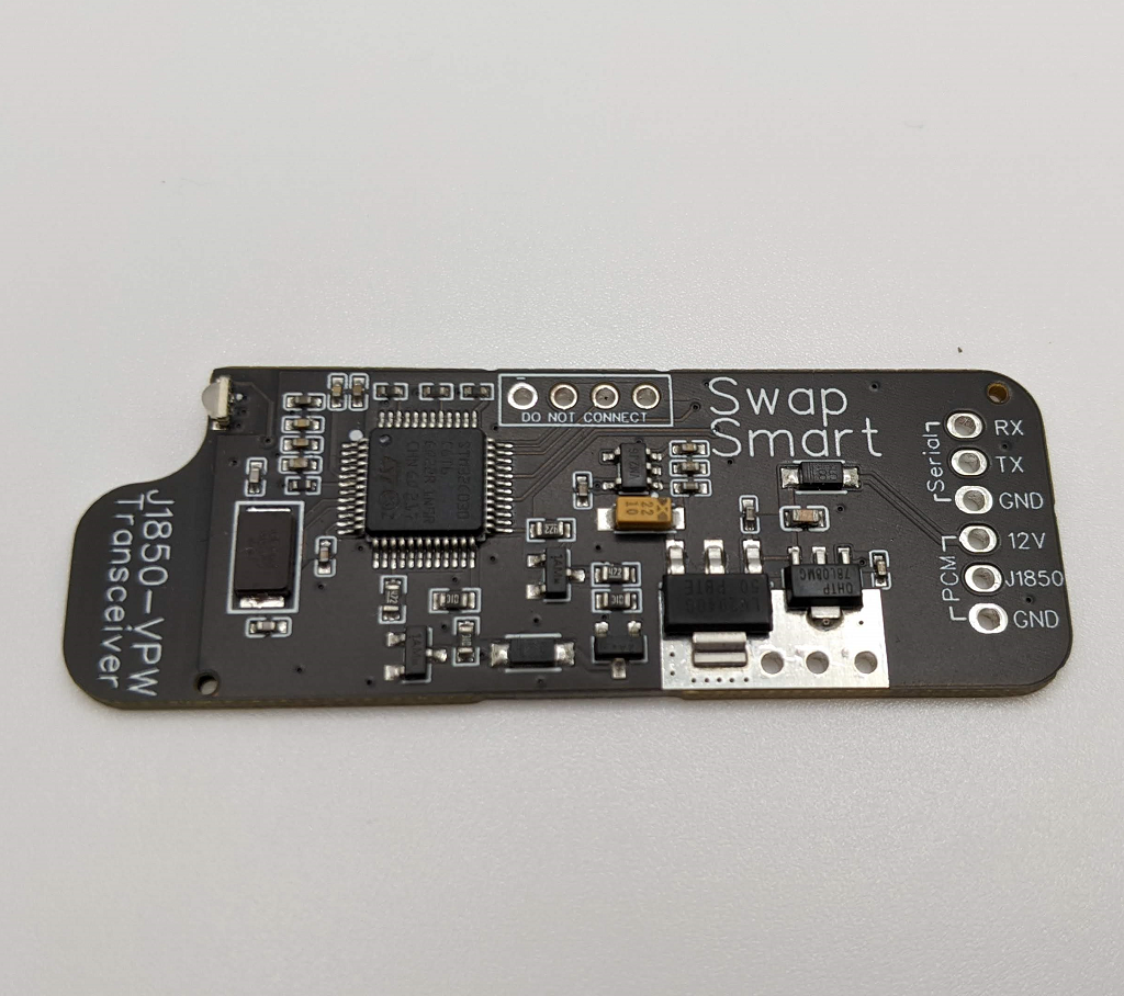
J1850 VPW Transceiver Interface
J1850 VPW Transceiver Interface
Product Downloads
J1850 VPW Transceiver Library & Example (Arduino IDE)
Couldn't load pickup availability
Share
Product Description
The J-1850 VPW Transceiver was designed for those who are either interested in controlling or reverse engineering a vehicles data bus that is using the J-1850 VPW protocol. Unlike most scan tools that support this protocol, this device is intended for use with a micro controller such as an Arduino Uno, Mega, ESP32, STM32, Raspberry Pi or any other type of device that supports UART serial data.
This J-1850 VPW Transceiver board does not require any programming, however, this device is not intended to be used on it's own. You will need to interface this with some type of micro controller and write your own program for that micro controller to be able to read or write messages using serial data to communicate with this device .
This device is compatible with both 3.3 volt 5 volt device that support either 9600 or 115200 baud rates. This device does not require a library to interface with, however we do offer an Arduino IDE compatible library if you would like to simplify how you interact with the board. Of course, if you prefer you can also communicate with the board directly, it does use a rather simple message format(outlined below) and the use of a library is not really needed.
To send a message:
uint8_t TxMsg[] = {0x00, 0x05, 0x48, 0x10, 0x1A, 0x01 0x0B}
0x00 is the 1st byte, its value must always be 0
0x05 is the size of the message that will be sent, in this case 5 bytes
0x48 Message Priority
0x10 To Device ID
0x1A Device ID requesting the message
0x01, 0x0B is requesting a mode 1 RPM data pid
To read a message the board uses the same format, the first byte will always be 0x00 followed by the message size. If the size byte was 0x08 then you would read the next 8 bytes. The J1850-VPW checksum will not sent over serial. After you have read the complete message you can either send a message or continue looking for the next message to read.
This device does not include any type of header terminals, however it is capable of supporting multiple types of connections. The header spacing has been designed so that is can be used with 2.54mm or 2.5mm spaced terminals as well as accept 22 gauge wire.
This device is not intended to be used as a formal scan tool, the devices message buffer will only supports message sizes up to 255 bytes and this device does not support 4x high speed mode because it is not needed(or used) outside of module programming.
The input power supply for this board has a normal working range of 11 to 15 volts. This board can handle a 16 volt power supply for a short periods of time although the onboard voltage regulator will begin to get pretty warm.
The VPW circuit is designed to work with 7 to 8 volt signal lines and can with stand up to 10 volts on the data line with out damage, if you exposing the data line to voltages above 10 volts it will likely damage the board.
The serial data lines are compatible with a 3.3 volt devices and will also be compatible with most(if not all) 5 volt devices. Exposing either the TX or RX lines to voltage levels above 5.2 volts will damage the boards processor.
Note: This is a DIY device that requires the user to write their own program to interact with this hardware. SwapSmart will not answer questions or provide any asstiance when using this device, we have provide a working example of how to interact with this hardware that you are free to modify to suit your needs. Beyond the example we provide, we do not offer any other type of support for this device.
Due to the design and potential uses of this device, this product does not come with any type of warranty. To make sure you do not revive a defective board, we test each board by hand using the example program we provide with a GM P01 ECU to verify the hardware works correctly before the product is shipped.